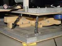
Motion Platform (base)

Rocker. The base is composed of a 35’’x35’’ rocker in an X form to rock in both directions Left/Right and Front/Back. The rocker is cut in the woodshop in UF in a way where it can be blocked by wooden blocks for safety while sitting in and going out. Two pieces of wood are bolted together to make it more stable.
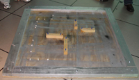
 Sliders.
On top of the Rocker three 24’’ x 24’’ squares
on top of each other where between the 1st and the second pieces
we have 3 parallel rails to slide from Left/ Right. Between the 2nd and
the 3rd
pieces we have another 3 parallel rails to slide Front/Back .
Sliders.
On top of the Rocker three 24’’ x 24’’ squares
on top of each other where between the 1st and the second pieces
we have 3 parallel rails to slide from Left/ Right. Between the 2nd and
the 3rd
pieces we have another 3 parallel rails to slide Front/Back .
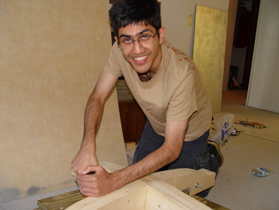
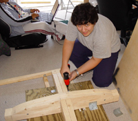 Rocker + Sliders.
The rocker and sliders are joint together by L-shaped metal
pieces with 4 each on each side of the rocker, so the total
of L shaped pieces is 8 with 4 screws each (total of 32 screws).
Rocker + Sliders.
The rocker and sliders are joint together by L-shaped metal
pieces with 4 each on each side of the rocker, so the total
of L shaped pieces is 8 with 4 screws each (total of 32 screws).
A 35’’x48’’ platform is mounted by 4 long and thick bolts, washers and hex-nuts in the center. The bolts attach the top wooden platform of the slider. This is the main platform where the chair is mounted and the user steps on this platform to get in.
Another perforated sheet is sprayed silver and is mounted on top of this platform just for the aesthetics. It is mounted by tens of non Philips screws that look hexagonal. Mainly used for the aesthetics.
 Motion Constraint. The
rocker rotates along the Z axis and we don’t want this effect.
Another 48’’x48’’ platform is put on the floor
under what we built so far and 4 wooden blocks are added to
this platform so the rocker fits in to stop the rotation.
Motion Constraint. The
rocker rotates along the Z axis and we don’t want this effect.
Another 48’’x48’’ platform is put on the floor
under what we built so far and 4 wooden blocks are added to
this platform so the rocker fits in to stop the rotation.
We also noticed that the motion range is too big for our needs,
so we attached 4 hooks on the corner of the main platform and
another 4 hooks are attached to the corners of the bottom platform
too. 4 super strong sports rubber bands go through the top and
bottom hooks of each corner attaching the top and bottom platforms
together on the 4 corners.
 This works but now the load is still on the center and the rubber bands
are pulling from 4 corner in the 4 directions, so the bottom platform started
buckling and the rotation problem is back. Worried of the safety, we bought
4 strong 48’’ wooden pieces and attached those to the edges
of the bottom platform. Now it’s stable but a little rotation is
still there, to fix this we put some high friction rubber material between
the floor and this platform …. And problem solved !!
This works but now the load is still on the center and the rubber bands
are pulling from 4 corner in the 4 directions, so the bottom platform started
buckling and the rotation problem is back. Worried of the safety, we bought
4 strong 48’’ wooden pieces and attached those to the edges
of the bottom platform. Now it’s stable but a little rotation is
still there, to fix this we put some high friction rubber material between
the floor and this platform …. And problem solved !!
Chair
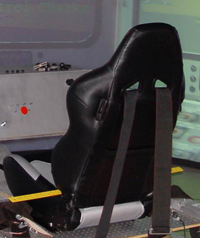 The chair is mounted on top of the 35x48 platform by 4 long
screws on the rail that come built-in the chair.
The chair is mounted on top of the 35x48 platform by 4 long
screws on the rail that come built-in the chair.
Shakers
 We are using two source of vibration, the first is the built-in
NAVE vibrators under ground. Since the physical platform
is made of many layers, the vibration signal arrives weak so we added 2
more shakers, one
on each side, under the 35x48 platform. They are hooked up
with 4 screws each.
We are using two source of vibration, the first is the built-in
NAVE vibrators under ground. Since the physical platform
is made of many layers, the vibration signal arrives weak so we added 2
more shakers, one
on each side, under the 35x48 platform. They are hooked up
with 4 screws each.
Harness
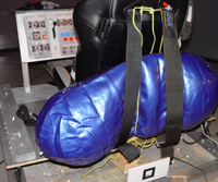 A five point harness is used to strap the user in the chair and to feel
the pressure of the launch later on. The harness is screwed
to the main platform so each end of the 5 straps is fixed on one side.
A strong sports
balloon is inserted between the two back straps and the chair,
this balloon is inflated using an inflator later so the user feels the
pressure on the
chest. A neck pillow is put between the harness and the user’s
neck so when the harness is tightened, he will still feel the pressure
without
hurting his neck.
A five point harness is used to strap the user in the chair and to feel
the pressure of the launch later on. The harness is screwed
to the main platform so each end of the 5 straps is fixed on one side.
A strong sports
balloon is inserted between the two back straps and the chair,
this balloon is inflated using an inflator later so the user feels the
pressure on the
chest. A neck pillow is put between the harness and the user’s
neck so when the harness is tightened, he will still feel the pressure
without
hurting his neck.
Interaction: Keyboard + Joystick
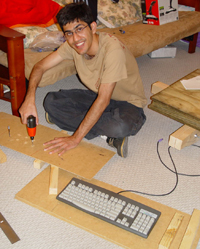 The user is asked to press 7 buttons in a row to check the controls. These
buttons are NOT regular keyboard buttons. The front panel consists
of a wooden frame attached to the main platform. On the horizontal
part of the
frame two hinges attach the platform to the wooden base that
supports the keyboard. Now the base rotates about the frame
to make the panel slanted
and movable so the user can get in the chairs without the need
of too much space. On top of the keyboard base sits the actual
keyboard and on top
of the keyboard there is another wooden plate that looks from
the outside like the cockpit that the user sees on the screen.
The user is asked to press 7 buttons in a row to check the controls. These
buttons are NOT regular keyboard buttons. The front panel consists
of a wooden frame attached to the main platform. On the horizontal
part of the
frame two hinges attach the platform to the wooden base that
supports the keyboard. Now the base rotates about the frame
to make the panel slanted
and movable so the user can get in the chairs without the need
of too much space. On top of the keyboard base sits the actual
keyboard and on top
of the keyboard there is another wooden plate that looks from
the outside like the cockpit that the user sees on the screen.
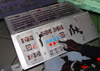 A
texture is printed and pasted on the wood. The top and bottom
plates are perforated
and bolted with 4 bolts and the keyboard is between both plates.
The top plate is
drilled and 7 actual buttons touch the keyboard using a retractable
pen mechanism. Actual pens were cleaned and inserted through
the holes to touch
the keys from the keyboard side and a spring on the other side
make the pen release the button after it’s pressed. The top aesthetics
of the button are red circular and blue square wooden pieces
glues on the pens with a plastic glue gun.
A
texture is printed and pasted on the wood. The top and bottom
plates are perforated
and bolted with 4 bolts and the keyboard is between both plates.
The top plate is
drilled and 7 actual buttons touch the keyboard using a retractable
pen mechanism. Actual pens were cleaned and inserted through
the holes to touch
the keys from the keyboard side and a spring on the other side
make the pen release the button after it’s pressed. The top aesthetics
of the button are red circular and blue square wooden pieces
glues on the pens with a plastic glue gun.
 Thejoystick is another
mean of interaction used when docking to the space station.
It is mounted on its own black painted box.
Thejoystick is another
mean of interaction used when docking to the space station.
It is mounted on its own black painted box.
Tracking marker
A marker is attached to the base that rocks and is tracked
optically by a web-cam.
the marker is not attached directly on the platform because
it gets out of the camra’s field of view, so a wooden piece extends
from the rocker outward so the marker is attached to it without being blocked
for certain positions.
Safety factors
Safety is out priority number one, so whenever 2 screws are enough we were putting 5 to be really solid and support different body weights and motions. Whenever 2 small rails are enough, we put 3 big one. Wooden blocks are used to lock the rocker when the user gets in.
Aesthetics
All the wooden blocks are sprayed silver before attaching them. All non functional buttons are sprayed black and all functional one are painted blue or red using acrylic paint. A perforated board is sprayed and attached just for the aesthetics of it so it looks like metal.
Comfort & Feeling
The racing chair is used to have the same sitting feeling. A pillow is used under the harness so the tightened harness does NOT hurt the user’s neck A foot rest is attached in the front so tall users can sit there comfortably. And guess what, this piece is made out of the complementary parts cut out of the rocker.
3D Models & Video
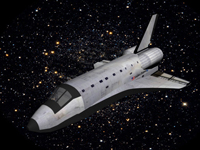 All the models including the cabin, space shuttle, space station, solar
system and asteroids were created realistically using 3D Studio Max and
based on photos of the originals. The models are exported into Open Flight
format and later imported into Vega Prime. The briefing video also involved
an animation created in 3D Studio max. The editing of the briefing video
was done with Adobe Premiere. Cool Edit was used for editing sound clips.
All the models including the cabin, space shuttle, space station, solar
system and asteroids were created realistically using 3D Studio Max and
based on photos of the originals. The models are exported into Open Flight
format and later imported into Vega Prime. The briefing video also involved
an animation created in 3D Studio max. The editing of the briefing video
was done with Adobe Premiere. Cool Edit was used for editing sound clips.